 |
The Plexus Parasound P/PH-100
Modifications
email me |
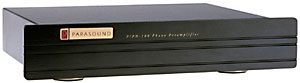 |
PPH-100 Phono Preamp Features:
Works with all line drive preamplifiers
RIAA curve accurate to 0.25 dB
Ultra low distortion
Internally selectable adjustment for moving coil or moving magnet
Analog Devices operational amps
Audiophile grade resistors and capacitors
Computer grade glass epoxy circuit board
Gold-plated RCA jacks
9 1/2" width front panel
Removable IEC AC cord
1 rack space height front panel
Two unit fastening hardware available for side-by-side rack mounting
Specifications:
Input Sensitivity: moving magnet: 2 mV; moving coil: .5 mV
Input Impedance: 47k ohms
Input Overload: 220 mV, I kHz mm
RIAA Accuracy: 0.25 dB, 20 Hz - 20 kHz
S/N Ratio: 72 dB, ref 5 mV input
Dimensions: w 9 1/2" x h 1 3/4" x d 7", h 2 3/8"
with feet
Net Weight: 3 lb.
|
Special thanks to Klaus Böning for his help with some of the calculations
and the finer details of opamp design. Klaus has designed a preamp which I urge
you to explore. His page was an inspiration for this page and I couldn't have
made this preamp as good as it is without his help. http://www.klaus-boening.de
The Parasound P/PH-100 is an inexpensive
phono preamp that has an unusually good sound in it's price range. Taking a
look at the circuit, there is some good engineering here, with two gain stages,
a passive RIAA network and a little active before the second gain stage. Measuring
the values of the components in the RIAA section, it seems as if Parasound matched
these because they are very accurate. This is one big reason why this preamp
sounds so good.
There are many ways to improve on
this circuit. In these mods, many refinements take place but keep to the original
circuit topology. Namely:
| replace the stock opamps with
faster, quieter, FET input burr-brown op amps NE5534's with OPA637BP and
the AD712 with OPA2134 |
| added 4700uF per each rail after
the regulators, added 0.1uF HF bypass WIMA caps on all the opamp power rail
pins (prevents oscillation) |
| replaced all the RIAA parts
with hand matched parts to 0.5% to spec and 0.1% across channels |
| added the 4th time constant
50kHz cutoff in the RIAA network to conform to unpublished standards in
cutting lathe specs (ie. cutting lathes cut off at 6db/oct at 50kHz to prevent
head stress, this same cutoff is not used generally in RIAA networks but
it helps to clean up imaging lots of research on this out there) |
| the final gain stage, now using
a FET opamp, needs to have it's non-inverting input, which was normally
to ground, be impedance matched with the inverting input. a guy in germany
helped me with this he calculated the impedance of the RIAA network and
feedback loop to be around 18k. so i added an 18k resistor in to ground.
this really made the sound warmer by reducing high-order distortion produced
by the imbalance. |
| remove the RF filter on the
input by removing R1/2 and C1/2 and jumping the R1/2 pads. the holes for
C1/2 will become the input from the load module. |
| i added in a cartridge loading
feature so i could adjust the load on the cartridge. i used a 10PST dip
switch per channel and cascaded resistors so that loading can be adjusted
from 50 to 50k in 50 ohm increments. there is also a resistor per channel
that is responsible for the gain of the first stage i brought that resistor
out to a socket so that i can change the resistor to suit various gains.
again, important when changing the load because more load reduces the output
of the cartridge. |
| replace the two 22uF electrolytics
with PP; I am using Solen Fast Caps for this application - matched pair.
NON-POLAR! |
| moved the feedback resistors
right to the pins on the dip socket to eliminate oscillations with the 637's.
not required for use with 604's. |
| added a switchable external
battery power supply based on 8 6V/4aH sealed lead acid cells providing
+-12V at 8Ah. FYI: each supply rail draws 24mA. |
| a faraday cage around the transformer |
I can do these
modifications for you for $500US which includes all parts and labour. These
modifications truely transform this preamp. The mods do not include the switchable
loading block however I will set the load to match your cartridge.
Some Notes:
The gain of the second stage (AD712 replaced with OPA 2604/2134) is 90. The
gain of the first stage is calculated to be 1+(R5 / (1/((1/R7) + (1/R23))))
or 1+(R5/(sum of the two gain sink resistors which are in parallel)). so by
replacing R23 with any value the gain of the first stage is 1+(2700/(1/((1/470)+(1/R23)))).
gain in dB is 20*log(gain). so the gain for the second stage is 20*log(90) =
39dB. the gain for the first stage, using stock values (R23=0 for MM and 47
of MC) is MM=16dB and MC=32db for a total gain of MM=55dB and MC=71dB.
by replacing R23 you can change the gain of the first stage which will change
the total gain of the preamp to suit your needs.
i have tried OPA637BP's in the preamp and they work pretty well with only a
minimal amount of oscillation. before you go an invest in the almost $30US per
637, check here for further details. it would be nice to completely eliminate
the oscillations. I am working on that.
UPDATE 1 March 2002
R5 and R6 are the first stage feedback
resistors. The oscillations when using OPS637BP can be completely eliminated
by moving these resistors directly to the pins of the opamp (soldered underneath).
Simply remove them and resolder between pins 2 and 6 on the sockets.
Hum can be significantly reduced
by using a bettery supply. The use of sealed lead acid cells will result in
lower maintenance. It is fine to use two 12V cells for a +-12V supply. These
will be easier to charge as 12V charges are readily available. Put the battery
supply after the voltage regulators. In my unit, I left the internal AC supply
intact and installed a switch that allows switching between the internal AC
supply and the external battery supply. When there is no AC connected, the switch
acts as an on/off switch.


The 4th time constant: the RIAA spec doesn't officially mention the 4th time constant
which is another eq filter which is a cutoff from 50kHz up at 6db/octave. This
was used to relieve stress on the cutting lathe. There are many links on the web
about this time constant. Here are a couple comments:
Extract from:
The Analog Addicts Phono Preamp
By Thorsten Loesch
The RIAA equalisation shall have the best accuracy that can be obtained using
of-the-shelf parts and MUST implement a replay curve which mirrors the curve
used when cutting a record, NOT THE documented RIAA Curve, which is incorrect.
The Neumann Cutting Amp Manual states that the boost in high frequencies is
being rolled off at about 50kHz. Neumann cutting lathes and amps are pretty
much the Industry Standard, we can assume this as being a de-facto standard.
Any kind of warp-filtering is bound to introduce low frequency phase shifts.
Most decent record players use clamps to minimize warp related effects, and
no-one should need attenuation of any rumble, so the misguided IEC amendment
to the RIAA curve must be avoided, and the absolute lower cutoff point of
the phono headamp should be as low as possible. The lower cutoff should be
a single dominant pole at 5Hz or less. With current off-the-shelf parts of
moderate cost but high quality, an RIAA accuracy of +/-0.1db or better can
be achieved in the midband. Due to the additional high frequency breakpoint
we expect an error (with respect to the standard RIAA curve) of about +0.25db
@ 20kHz.<
Extract from:The secrets
of the phono stage
By Allen Wright4
Add the missing Time Constant!
The 75µS networks in all these designs (except mine) fall at 6 dB/oct forever...
OK, this may be the RIAA spec but if you think of the record cutting process-can
they really boost at 6dB/Oct. from 2122Hz on up forever? Back in the 70's
we called some cutting equipment service departments and found they do roll
off this boost with achicane at around 50kHz (3.18µS)-so as to keep cutter
head warranty claims to a minimum or whatever. And when this is done (in reverse)
in a preamp, it flattens out that 75µS drop to hell and restores much of the
air and naturalness that's on the master tape. This is the purpose of R3 on
the FVP5 map, and it's pretty easy to try yourself: a/ Find the cap used for
the 75µS roll off (i.e. 820 or 1000 pF in Diego's) b/ Calculate what R you
will need to get 3.18µS in conjunction with this cap (= 3K87 or 3K18 in Diego's)
c/ Fit it in series with the cap-and tweak for sonic satisfaction and exact
upper octave ch to ch balance. N.B. It's phase accuracy across all four bands
that gives you that real life image the bottom feeders say don't exist!
Now, how do we add this into the
Parasound? Very simple! Add a 1000 ohm resistor after the point where C5/C7
connect. You will have to cut a trace. This will put the cut off at around 43.7kHz
which is almost ideal. Make sure to match the resistors across the channels
at least withing 0.1%.


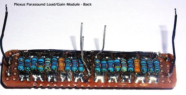
The Load/Gain Module
Uses resistors 50, 100, 200, 400,
820, 1600, 3200, 6400, 12k, 25k soldered across each switch and then joined
staggered to facilitate a series resistor of aroun 50k. Turning a switch ON,
shorts that's resistor taking it out of the chain allowing values from 50 to
50k in 50 ohm increments.


Completed Unit


Cartridge Loading
For an excellent description of cartridge
loading and calculators to help you figure out the optimal loading go here http://www.hagtech.com/loading.html.
You will have to know as closely as possible the capacitance of your arm cable
including the arm wire as well as the impedance of your cartridge. If you have
a capacitance meter you can measure the capacitance by disconnecting the cartridge
at the headshell and measure from the rca jacks on one channel.